This is the multi-page printable view of this section. Click here to print.
Modules
- 1: Ethernet Module
- 2: IO Module
- 3: KHBS Module
- 4: Mainboard
- 5: Power Module
- 6: WLAN Module
1 - Ethernet Module
Configuration
The Ethernet module can be configured via Control UI:
http://noreya-nexus.local/nexuscontrolui/network/ethernet
The assigned addresses can be found under:
http://noreya-nexus.local/nexuscontrolui/network
Label description
| Label | Led On | LED off | LED blinking |
|---|---|---|---|
| FDX | Full Duplex mode | Half Duplex mode | |
| LINK | Data Link Layer connection ok | no connection (no cable connected/switch offline) | |
| ACT | connected (no data transfer) | no connection | data transfer ongoing |
| 1G/10M | 10M=10Mbit mode, 1G=1000Mbit mode | NA | |
| 1G/100M | 100M=100Mbit mode, 1G=1000Mbit mode | NA | |
| FAIL | Voltage limits exceeded (may light up during plug-in) | voltage ok | |
| 2V5 | 2.5V on | 2.5V off | |
| 3V3 | 3.3V on | 3.3V off |
2 - IO Module
Openhab detection
Using IO Modules over the network
The IO Module is fully network compatible.
This means you can detect and use it from any openHAB instance in the network e.g:
- A server running openHAB can access an IO Module connected on a Nexus in the network
- A Nexus can access an IO Module form another Nexus
By default mDNS is used to detect devices on the network.
The first Nexus is called noreya-nexus.local in the network, the second noreya-nexus-2.local and so on.
This numbering is done by the mDNS protocol and in general stable based on the IP/MAC addresses.
However, if one of the systems go offline the protocol renumbers the hosts e.g:
If there are noreya-nexus.local, noreya-nexus-1.local and noreya-nexus-2.local and noreya-nexus-1.local goes down noreya-nexus-2.local becomes noreya-nexus-1.local.
The openHAB plugin stops if detects such a change to avoid further problems.
Qualified personal
Must only be used and installed by qualified personal
Cable length
The maximum cable length for the IO Module is 3m. Shielded cable must be used for PWM mode.
Using IO Modules over the network
For this reason, it is highly recommeded to assign static IPs and or hostnames (via your router) and setup the openHAB things manually!Network detection
Label description
| Label | Led On | LED off | LED blinking |
|---|---|---|---|
| 1 | Output/PWM mode (active) | Input mode | |
| 2 | Output/PWM mode (active) | Input mode | |
| 3 | Output/PWM mode (active) | Input mode | |
| 4 | Output/PWM mode (active) | Input mode | |
| 5 | Output/PWM mode (active) | Input mode | |
| 6 | Output/PWM mode (active) | Input mode | |
| OCR | Overcurrent event | ||
| OVP | Over-/Undervoltage event |
3 - KHBS Module
Basic
The KHBS Module is automatically detected and configured when connected the first time.
The configuration can be changed via Control UI:
http://noreya-nexus.local/nexuscontrolui/network/khbs
The openHAB bridge is automatically added.
Label description
| Label | Led On | LED off | LED blinking |
|---|---|---|---|
| BACT | Bus online | no transfer | Bus data transfer ongoing |
| TEMP | Temperature limit reached | Temperature ok | |
| BUSV | Bus voltage ok | Bus voltage too low | |
| VCC | TPUART VCC ok | ||
| VDP | TPUART VDP ok | ||
| UTX | USB/UART sending | ||
| URX | USB/UART receiving | ||
| UVCC | USB/UART VCC ok |
How to wire it up [TODO]
How to open the firewall for Programming [TODO]
Each KHBS Module can be used as IP Tunnel for programming.
However, common programming software is only able to detect on Tunnel per host (standard port) so only the KHBS Module on port 3761 [TODO Check port] is auto discoverd.
Others must be added manually.
Basic tutorial [TODO]
4 - Mainboard
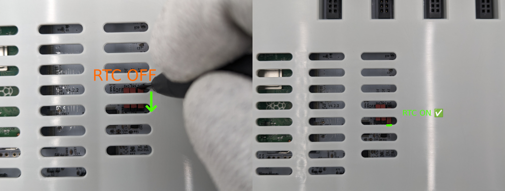
Enabling the RTC battery
Before you start up the Mainboard, make sure that the real-time clock battery is turned on. It is initially deactivated to save energy. To change this, use a small screwdriver to set the switch to the correct position. Also, ensure that all other switches are set to ‘OFF.’
Forcing the BMC in bootloader mode
You can put the BMC (not the CM) into bootloader mode by setting the bootloader switch to “ON” and doing a power cycle (a restart is not sufficient!).
Integrity of the RAID
The operating system runs on two SD cards in so called RAID 1 (mirroring) mode.
If one fails, the system continues to function.
There may be a degraded warning if:
- The two disks are not synced or syncing
- There is only one disk
- One disk is faulty
On first boot it takes 2-3 hours to complete the sync.
If the status has not changed after 3 hours, you should download the latest backup immediately (or create one now).
Do not reboot the system unless you found the issue!
Troubleshooting
You should investigate which SD card is faulty. Login via console and check:
cat /proc/mdstat
Syncing
If the disks are syncing a progess will be shown.
You can see the expected time to finish in the output.
If you restart the system during synchronization, it will start from the beginning.
Personalities : [raid0] [raid1]
md42 : active raid1 mmcblk1p2[2] mmcblk0p2[0]
      20832768 blocks [2/1] [U_]
      [>....................]  recovery =  0.9% (198656/20832768) finish=81.2min speed=4234K/sec
Faulty SD card
Personalities : [raid0] [raid1]
md42 : active raid1 mmcblk1p2[2](F) mmcblk0p2[0]
      20832768 blocks [2/1] [U_]
The “(F)” indicates the failed SD card.
In the above example “mmcblk1p2” is faulty which is SD card 1 on the Mainboard.
“mmcblk0p2” is SD card 0 on the Mainboard.
Integrity of the file system
The filesystem is checked for errors once a week (full metadata+data check).
If the status is degraded, you should download the latest backup immediately (or create one now).
Real-time clock (RTC) battery
The device contains an RTC which is powered by a CR2023 battery.
It is used to keep time during periods without power supply.
If the battery level falls below ~2.8 V, the battery should be replaced, otherwise the time will be lost during the power supply interruption.
Flash sdcards
See Maintenance / Flash SD cards
Replacing the SD card
See Maintenance / Flash SD cards
RAID limitations
Although the RAID ensures that the system continues to run, it has some limitations due to the Compute Module:
- The system only boots from SD card 0, if it is defective, it may not boot (create a backup and download it before rebooting!!).
- If you insert SD card 1 into SD card slot 0, the system will not boot because the boot partition is not formatted (will be fixed in the future)
How to install the Mainboard on a DIN rail [TODO]
Add instructions how to mount the Mainboard
How to connect using the serial port [TODO]
LED description
| Color | Label | Led On | LED off | LED blinking | LED blinking fast |
|---|---|---|---|---|---|
| Red | BMC warning | error appeared / reset | |||
| Green | BMC activity | BMC off | BMC active | BMC shutting down CM | |
| Green | 3V3 | voltage ok | |||
| Yellow | CM active | CM starting / in bootloader mode | CM off | CM active | |
| Yellow (USB) | Serial console | Serial console connected | No cable connected / Bootloader mode |
5 - Power Module
General
The Power Module should always be connected to the Mainboard powerless.
If it is connected powered on the Mainboard may not boot because of the voltage timing requirements.
Power Module fan
The module contains a PWM-controlled Noctua fan.
The fan is controlled by the Power Module or the Mainboard when the fan control service is active.
It cools both the Mainboard compute module and the Power Module itself based on a calculation of multiple temperature sensors.
It is not necessarily required for ambient temperatures <50°C, but improves the computing performance of the Mainboard and the service life of the Power Module.
If the measured fan speed is lower than the expected value, the fan is most likely not connected, stuck or defective.
It must be replaced as soon as possible to achieve the specified operating temperature range and performance!
Power Module fan maintenance
The Power Module has a fan which requires maintenance.
Despite the fact that the module may only be used in low-dust environments, dust may accumulate in the housing over time.
This must be checked every 12-24 months.
To do this, shut down the system and disconnect the power module from the mains voltage.
Remove the module from the mainboard. It is not necessary to disassemble the module.
Use a vacuum cleaner to remove dust from the ventilation slots.
Clean the ventilation slots of the Mainboard at the same time.
Power Module error counter
The Power Module continuously measures all supply voltages, currents and temperatures in order to detect faults.
If a limit is exceeded operation can not be guranteed and the Power Module hard resets the system.
It tries to write the cause of error into its storage. In some cases (hard shortcut on 12V rail) it may not be able to save the error.
If the error counter increases in a short period of time, you should check
- the AC input voltage (cheap UPS may cause this)
- the connections of the IO module
- the ambient temperature for issues.
You can view the counter via console on the device:
curl http://localhost/api/power/1.0/1/protectionlog
You can reset the counter via console on the device:
sudo systemctl stop nexus-drv-power
echo -en "\x01\x03\x06" > /dev/slot1
sudo systemctl start nexus-drv-power
| Label | Led On |
|---|---|
| top (AC connector side) | Power delivery: <= 100.0% (30W) |
| Power delivery: <= 87.5% (26.25W) | |
| Power delivery: <= 75.0% (22.5W) | |
| Power delivery: <= 62.5% (18.75W) | |
| Power delivery: <= 50.0% (15W) | |
| Power delivery: <=37.5% (11.25W) | |
| Power delivery: <= 25.0% (7.5W) | |
| Power delivery: <= 12.5% (3.75W) |
6 - WLAN Module
Configuration
The WLAN Module can be configured via Control UI:
http://noreya-nexus.local/nexuscontrolui/network/wlan
The regulatory country code must be set correctly and can be found under:
http://noreya-nexus.local/nexuscontrolui/system/settings#heading_regulatory_country
The module supports both client and access point mode, but only one at a time.
The assigned addresses can be found under:
http://noreya-nexus.local/nexuscontrolui/network